In this section
•How to Create a Scanning Cluster
•Verifying Cluster Operability
To create a scanning cluster that allows performing distributed scans (while scanning files or other objects), you need to have a set of network hosts with the Dr.Web Network Checker component installed on each host. To ensure that a cluster host not only receives and transmits data to be scanned, Dr.Web Scanning Engine must be installed on the host. Thus, to create a scanning cluster host, install at least the following components on the server (other components of Dr.Web Mail Security Suite that are installed automatically to ensure operability of the components listed here are not mentioned):
1.Dr.Web Network Checker (the drweb-netcheck package) is a component for receiving and sending data between hosts over the network.
2.Dr.Web Scanning Engine (the drweb-se package) is an engine for scanning data received over the network. The component may be absent; in this case, the host only transmits data to be scanned to other hosts of the scanning cluster.
The hosts that constitute the scanning cluster form a peer to peer network, i.e. each of the hosts, depending on the settings defined for the Dr.Web Network Checker component on this host, is capable of acting either as a scanning client (which transmits data for scanning to other hosts) or as a scanning server (which receives data for scanning from other hosts). With the appropriate settings, a cluster host can be both a scanning client and a scanning server at the same time.
Dr.Web Network Checker parameters related to scanning cluster configuration have names starting with LoadBalance.
How to Create a Scanning Cluster
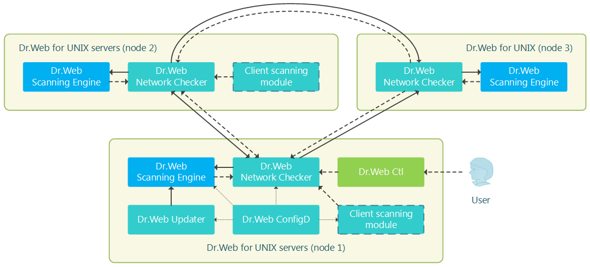
Let us consider the scanning cluster example displayed in the figure below.

Figure 14. Scanning cluster structure
In this case, it is assumed that the cluster consists of three hosts (displayed in the figure as host 1, host 2 and host 3). Host 1 and host 2 are servers with a fully-fledged Dr.Web product for Unix servers installed (for example, Dr.Web Gateway Security Suite or Dr.Web Mail Security Suite, the product type does not matter), and host 3 only assists in scanning files transferred from hosts 1 and 2. Therefore, only the minimal required component set is installed (Dr.Web Network Checker and Dr.Web Scanning Engine, other components that are automatically installed to ensure host operability, such as Dr.Web ConfigD, are not displayed in the figure). Hosts 1 and 2 can operate both as servers and scanning clients with regard to each other (perform mutual distribution of scanning load), and host 3—only as a server receiving tasks from hosts 1 and 2.
In the scheme, “Client scanning module” designates components of the servers that create scanning tasks for the Dr.Web Network Checker component. These tasks will be distributed (depending on the load balance) between local Dr.Web Scanning Engine and cluster partner hosts acting as scanning servers.
Only components that scan data not represented as a file in the local file system can act as the client scanning module. This means that the scanning cluster cannot be used for distributed scanning of files by the SpIDer Guard file system monitor and the Dr.Web File Checker component. |
To set up the specified cluster configuration, adjust Dr.Web Network Checker settings on all three cluster hosts. All of the following settings are provided in the .ini format (refer to configuration file format description).
Host 1
[NetCheck] |
Host 2
[NetCheck] |
Host 3
[NetCheck] |
Notes:
•Other Dr.Web Network Checker parameters (not mentioned here) are left unchanged.
•Change IP addresses and port numbers to relevant ones.
•This example does not use SSL for data exchange between hosts. To use SSL, set the LoadBalanceUseSsl to Yes, as well as set relevant values for parameters LoadBalanceSslCertificate, LoadBalanceSslKey and LoadBalanceSslCa.
To verify cluster operability in data distribution mode, use the following command on hosts 1 and 2:
$ drweb-ctl netscan <path to file or directory> |
While this command is being run, Dr.Web Network Checker scans files from the specified directory having distributed load between cluster hosts. To view statistics on network scanning for each host, output statistics of Dr.Web Network Checker with the following command before scanning:
$ drweb-ctl stat -n |
To interrupt outputting statistics, press Ctrl+C or q.